English

Direct Engineering Verdict: If you need an immediate engineering verdict on how to evaluate china ultra led display manufacturers without blowing your capital on dead pixels, overheating driver boards, or failed municipal electrical inspections, here is the direct baseline: partner exclusively with dedicated commercial fabricators that assemble with Flip-Chip Chip-on-Board (COB) or Micro-LED-in-Package (MIP), driven by pulse-width modulation (PWM) constant-current driver ICs supporting at least 3,840 Hz to 7,680 Hz refresh rates (Macroblock MBI5359, Chipone ICN2069, or Sunmoon platforms), housed in 5-axis CNC-machined die-cast magnesium-aluminum cabinets with six-axis planar micro-adjustment, and powered by common-cathode, fanless power supplies with active Power Factor Correction (PFC > 0.95).
Furthermore, your purchase agreement must legally enforce an uninterrupted 72-hour full-white and low-grayscale thermal aging run, single-bin color wavelength sorting within a 2-step MacAdam ellipse, and a minimum 5% batch-matched spare module allotment pulled from the exact same epitaxial wafer lot. If an overseas sales rep hesitates to provide unedited video documentation of their automated cleanroom SMT lines, dodges third-party laboratory EMC Class B compliance reports, or cannot furnish full-cabinet UL 62368-1 or CE certifications, walk away immediately no matter how attractive their per-square-meter quote looks.
Picture this realistic scenario: you run a commercial audio-visual integration firm, an electrical contracting business, or a digital signage agency based in London, Chicago, or Hong Kong. You just secured a high-profile contract to deliver a 165-inch ultra-fine pitch 4K command-center video wall for a financial trading floor or an executive boardroom. You submit RFQs across online sourcing channels, and within twelve hours your inbox is packed with digital catalogs from dozens of china ultra led display manufacturers. The pricing spread is staggering: one vendor quotes $1,100 per square meter, another quotes $2,400, and a third asks for $4,500. Every sales rep promises on their professional reputation that their facility in Shenzhen or Huizhou is a premier Tier-1 enterprise, their diodes never fail, and their cabinets fit together with zero physical seams.
What happens when your procurement team takes the lowball quote, wires the 30% deposit, and waits out ocean freight? The shipping crates arrive at your staging warehouse, your technicians hoist the cabinets onto the structural wall framework, and problems immediately start multiplying. When the master electrician hooks up grid power and switches on the panels, visible dark grid lines run throughout the entire video canvas because the cabinet edges deviated by just 0.15 mm from the factory casting molds. When your client pulls up a dark-grey financial spreadsheet at 15% display brightness, the screen dissolves into patchy red and green color blotches due to terrible low-grayscale driver calibration. Worse yet, when the client powers on their wireless conference microphones, a persistent high-frequency audio buzz echoes through the room because the cheap power units lack basic electromagnetic filtering. Fixing these defects on-site burns through your entire project margin within a week, while the overseas sales rep suddenly takes three days to reply to your urgent messages.
When we are installing ultra-fine pitch digital screens, saving a few thousand dollars on the initial invoice is never worth the nightmare of chronic field failures. But some friends want the lowest upfront price, what should you do then? Let's look down together and dissect the underlying semiconductor physics, mechanical engineering tolerances, factory auditing steps, and contractual safeguards you need to protect your capital.
When dealing with traditional outdoor billboards or standard indoor screens operating between P2.5 and P4.0, a slight mechanical tolerance gap of 0.2 mm or a minor thermal rise of 10°C rarely compromises the image. At that scale, viewing distances are long, and pixel density is forgiving. When you step into the territory of ultra-fine pitch displays—specifically pixel pitches ranging from P0.625 to P1.5625—the laws of physical tolerance and thermal dissipation become merciless.
Let's look at the mathematical reality of pixel density:
At P1.5625 mm, a display packs 409,600 individual pixels per square meter, totaling 1,228,800 discrete Red, Green, and Blue semiconductor dies.
At P1.25 mm, that density jumps to 640,000 pixels per square meter, representing 1,920,000 diode chips.
At P0.9375 mm, you are handling 1,137,778 pixels per square meter, which means over 3.4 million microscopic light emitters.
At P0.78 mm, the screen holds 1,643,721 pixels per square meter, putting nearly 5 million individual emitting points into a single square meter.
At this microscopic scale, any physical deviation between cabinet edges greater than 0.03 mm creates an immediate optical defect. If two cabinets sit just thirty microns too far apart, the human eye perceives a dark line cutting through the image; if they sit thirty microns too close, the adjoining pixels crowd together to create a distracting bright seam.
At that close range, viewers spot individual dead sub-pixels, subtle brightness variations between diode bins, and minor surface reflections immediately. You cannot hide manufacturing shortcuts behind viewing distance.
When evaluating catalogs from china ultra led display manufacturers, the packaging method used to bond the LED dies to the circuit board substrate is the most critical engineering choice you will make. Below is the breakdown of the competing technologies dominating the ultra-fine pitch market:
Standard SMD packages place individual Red, Green, and Blue dies inside a microscopic plastic cup with wire-bonded leads, which is then surface-soldered to the PCB. While SMD remains an affordable manufacturing route, it is mechanically fragile at pixel pitches below P1.5. Solder pads are tiny; a minor bump from an extraction tool during maintenance or a brush against a flight case corner can shear off twenty diodes instantly. Exposed SMD diodes also have zero barrier against airborne moisture, leading to silver migration and intermittent open-circuit pixel dropouts over time.
GOB is an intermediate upgrade over standard SMD. After traditional SMD modules are soldered and optically verified, an automated dispensing head coats the front surface with an optically clear epoxy or polyurethane resin. This creates an impact-resistant front face that can be wiped clean with a microfiber cloth and protects against moisture. GOB still retains the internal bond wires of SMD underneath the resin layer, meaning thermal dissipation remains restricted. If a diode burns out under a rigid resin coating, field repair is practically impossible without damaging adjacent copper traces.
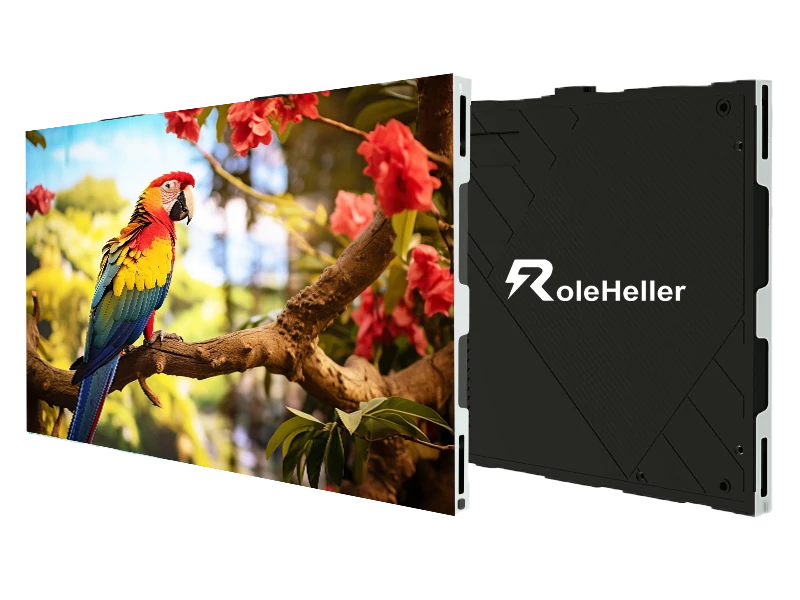
For ultra-fine pitches from P0.6 to P1.2, Flip-Chip COB is the benchmark for enterprise reliability. In Flip-Chip COB, bare semiconductor dies are mounted directly onto the circuit board face-down without any microscopic gold or copper wire bonds. The entire module surface is then encapsulated under a monolithic nano-optical polymer coating.
By eliminating bond wires entirely, Flip-Chip COB removes the number-one point of thermal and mechanical failure in LED engineering. Heat transfers directly from the semiconductor die into the circuit board's copper heat-sink planes, lowering operating temperatures by 10°C to 15°C compared to SMD. The finished surface achieves an IP54 or IP65 rating, resists static electricity shocks, wipes clean effortlessly, and yields contrast ratios exceeding 20,000:1 with deep, ink-black backgrounds.
MIP is the packaging evolution designed to bridge the gap between traditional SMT manufacturing and pure COB. In MIP, microscopic Micro-LED chips are pre-packaged into tiny discrete pixel units (such as 0404 or 0202 packages) with independent cathode and anode pads, pre-tested and color-binned at the chip level before being mounted onto standard circuit boards using high-speed SMT lines. MIP allows manufacturers to achieve the high optical contrast and wide viewing angles of Micro-LED while retaining the ability to swap and repair individual pixel packages on a standard rework station.
| Engineering Parameter | Standard SMD 1010 | Protective GOB | Enterprise Flip-Chip COB | Advanced MIP (Micro-LED) |
|---|---|---|---|---|
| Optimal Pixel Pitch Range | P1.25 – P1.87 mm | P1.25 – P1.56 mm | P0.625 – P1.25 mm | P0.4 – P0.93 mm |
| Physical Impact Resistance | Very Fragile (Shears easily) | High (Resin face absorbs shock) | Maximum (Continuous monolithic seal) | High (Individual package protection) |
| Front Ingress Protection | IP30 (Exposed leads) | IP54 (Moisture resistant) | IP54 / IP65 (Fully dust & water sealed) | IP54 to IP65 (Dependent on mask) |
| Static Contrast Ratio | 3,000:1 – 5,000:1 | 5,000:1 – 8,000:1 | 15,000:1 – 30,000:1 (True Black) | 20,000:1 – 40,000:1 |
| Surface Operating Temp | High (+18°C over ambient) | Moderate (+14°C over ambient) | Low (+6°C to +8°C over ambient) | Low (+7°C to +9°C over ambient) |
| Off-Axis Color Consistency | Shifts past 120 degrees | Moderate past 140 degrees | Flawless up to 170 degrees | Flawless up to 170 degrees |
| Field Pixel Repairability | Moderate (Hot air station) | Extremely Difficult (Stripping resin) | Factory Return / Module Swap | High (Individual package rework) |
| Average Operational Lifespan | 50,000 hours | 70,000 hours | 100,000+ hours | 100,000+ hours |
| Relative Production Cost | Baseline (1.0x) | 1.15x – 1.25x Baseline | 1.45x – 1.80x Baseline | 1.60x – 2.10x Baseline |
One of the most common complaints from end-users installing ultra-fine pitch screens in executive suites or control rooms is that dark backgrounds look terrible. When a screen runs at full blast in an exhibition hall, colors pop and contrast looks sharp. But inside a dimmed conference room, running a display at 800 nits will cause intense visual fatigue for anyone sitting six feet away. The display must be dimmed down to 100 to 150 nits.
Here is the problem: when conventional driver ICs are dimmed down to 10% or 15% of their rated output, their pulse-width modulation bit depth collapses. A driver rated at 16-bit grayscale at 100% output might drop to 10-bit or 8-bit performance at low brightness levels.
The visual result is immediate and ugly:
Smooth gradients posterize into distinct, stepped bands of color.
Subtle drop-shadows on corporate presentation decks turn into muddy, blocky patches.
Low-light video scenes lose shadow detail completely.
Off-axis viewers notice subtle red, green, or blue tinting across uniform grey backgrounds.
When negotiating specifications with china ultra led display manufacturers, you must look closely at the driver integrated circuits. Demand constant-current driver ICs specifically engineered for fine-pitch low-grayscale fidelity, such as the Macroblock MBI5359 / MBI5264, Chipone ICN2069, or Sunmoon SM16380. These high-spec chips incorporate internal grayscale enhancement algorithms that maintain true 16-bit linear grayscale output even when the screen is dimmed to 80 nits. They also feature integrated phantom-line suppression circuits and open-circuit detection to isolate caterpillar failures—preventing a single blown diode from pulling down an entire horizontal row or vertical column into a bright, uncontrollable streak.
A practical testing method I often use during sample evaluations: load a 16-step linear greyscale ramp pattern onto the screen, drop the system master brightness to 10%, and slowly walk across the front of the display. If the transition between dark-grey blocks flickers, shows color stepping, or exhibits color shifts at a 45-degree angle, the driver architecture is inadequate for corporate or broadcast applications.
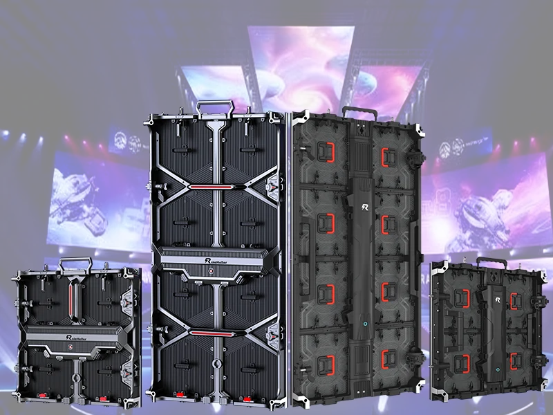
You can buy the best Flip-Chip COB modules in the world, but if they are mounted to flimsy, poorly machined cabinet frames, your finished video wall will look like a patchwork grid of visible seams.
Standard rental screens or budget fixed-install cabinets use raw die-cast aluminum frames pulled straight out of casting molds without secondary machining. When molten aluminum cools in a mold, it experiences uneven shrinkage and thermal contraction. Raw cast cabinets often suffer dimensional tolerances of ±0.2 mm to ±0.4 mm. When you stack eight or ten of these cabinets together, that cumulative dimensional variance makes a seamless finish physically impossible.
A legitimate tier-1 manufacturer of ultra displays takes a heavy die-cast blank and passes it through an automated 5-axis CNC milling center. The mating edges, locator pin holes, and module mounting faces are milled down to a precision tolerance of ±0.01 mm.
Look for these critical mechanical elements when inspecting cabinet samples:
Six-Axis Front Planar Micro-Adjustment: Each cabinet junction must include mechanical leveling adjustment points accessible directly from the front face using an Allen key. This allows your installation crew to fine-tune X, Y, and Z-axis planar alignment, compensating for uneven structural wall studs without needing to slide plastic shims behind the mounting brackets.
Hardened Steel Dowel Locating Pins: High-precision CNC-ground steel locating pins ensure that when cabinet B docks against cabinet A, the internal magnetic modules seat in exact alignment with zero lateral play.
Floating Neodymium Magnetic Module Seats: Modules should float slightly on spring-loaded magnetic pillars. This design allows modules to self-align against adjacent tiles rather than being rigidly locked to a slightly imperfect chassis.
Integrated High-Speed Blind-Mating Connectors: High-density displays should never use loose flat ribbon cables dangling between internal boards. Look for gold-plated, board-to-board blind-mating connectors that pass data and DC power directly when the module snaps into place. This eliminates pinched data cables and reduces electromagnetic interference.
Pure Electric Vacuum Extraction: Tiles must be removable using an automated, handheld electric vacuum tool that pulls the module straight out perpendicular to the wall. Manual mechanical levers, prying screwdrivers, or suction cups that require manual rocking will chip the delicate edge pixels of neighboring modules.
Thermal buildup is the primary cause of electronic failure in ultra-fine pitch displays. In an enclosed boardroom or a 24/7 security operations center, an LED wall drawing 4,000 watts acts as a giant space heater, forcing facility teams to install expensive dedicated air-handling units and generating intrusive ambient fan noise.
The vast majority of cheap P1.2 and P1.5 displays still rely on traditional Common Anode power architecture. In a common-anode circuit, a single 5V or 4.2V DC power rail feeds the Red, Green, and Blue semiconductor dies simultaneously.
Let's look at the electrical mismatch:
The Red LED die requires an operating forward voltage of only 1.8V to 2.1V to emit light.
The Green and Blue dies require between 2.8V and 3.2V.
When you force a 5.0V rail to power a Red diode that needs only 2.0V, the remaining 3.0V of electrical potential turns entirely into thermal waste.
Modern enterprise-grade systems from reputable china ultra led display manufacturers utilize Common Cathode power distribution. In a common-cathode circuit, the power supply splits into independent electrical rails: a dedicated 2.8V rail feeds the Blue and Green diodes, while an isolated 1.8V rail supplies the Red diode.
This engineering separation delivers massive operational advantages:
Total power consumption drops by 25% to 40% under typical video playback.
The operating temperature on the screen surface drops by 10°C to 15°C, eliminating the uncomfortable heat that radiates toward viewers sitting near the screen.
Because the Red diodes are not subjected to chronic thermal overdriving, common-cathode architecture prevents the localized red-channel lumen decay that causes older LED screens to shift color and turn sickly yellow-green after three years of operation.
| Component Specification | Tier-3 Cut-Rate Workshop | Tier-2 Standard Commercial | Tier-1 Enterprise OEM |
|---|---|---|---|
| Wholesale Price (P1.25 COB) | $1,200 – $1,600 / m² | $1,900 – $2,600 / m² | $3,200 – $4,800+ / m² |
| Packaging & Diode Spec | Standard SMD 1010, copper wire | 4-in-1 Mini-LED or basic COB | Full Flip-Chip COB / MIP, Gold pads |
| Color Sorting & Binning | Mixed diode bins (Batch surplus) | Single-bin (3-step MacAdam) | Single-bin (2-step MacAdam ellipse) |
| Driver IC & Processing | Basic dual-latch, 1,920 Hz | Chipone ICN2059, 3,840 Hz | Macroblock MBI5359, 7,680 Hz |
| Grayscale at 15% Nits | 10-bit (Visible banding & noise) | 14-bit (Acceptable gradients) | 16-bit Pure Linear Grayscale |
| Chassis Fabrication | Raw die-cast, manual spray coat | 4-axis CNC die-cast aluminum | 5-axis CNC Magnesium-Aluminum |
| Mechanical Seam Variance | ±0.15 mm (Visible dark seams) | ±0.04 mm (Minor alignment) | ±0.01 mm (Surgical zero-gap) |
| Power Supply Architecture | Common Anode 5V, noisy fans | Common Cathode, standard fans | Common Cathode, fanless, PFC > 0.95 |
| Controller Architecture | Generic unbranded cards | NovaStar A5s Plus / Colorlight | NovaStar Armor A10s Pro / Brompton |
| EMC & Safety Compliance | Self-declared "CE" sticker | Component-level UL power supply | Full-Cabinet UL 62368-1 & FCC Class B |
| Annual Pixel Failure Rate | Over 50 PPM (Frequent service) | Under 10 PPM (Manageable) | Under 2 PPM (Enterprise grade) |
The Component-Only Safety Certification Scam: A supplier proudly presents a PDF document displaying a recognized UL or CE testing mark. When you inspect the certificate details and file numbers, you find that only the internal power supply unit holds a component-level UL recognized mark (UR). The completed video cabinet—including the high-speed driver circuit boards, internal power cabling, and enclosure fire ratings—was never tested as a unified appliance. If your installation is subject to municipal electrical sign-offs in North America or Europe, building inspectors will red-tag the job site, leaving your display dark until an expensive field evaluation is performed.
Mixed-Bin Diode Patchworking: During semiconductor wafer fabrication, LED dies naturally produce variations in forward voltage, peak wavelength, and lumen output. Tier-1 manufacturers purchase tightly sorted single-bin diode lots to build an entire customer order. Cut-rate assemblers buy discounted surplus bins from multiple factory runs. On dynamic video content, the display might look passable; but the moment your client pulls up a solid white slide or a uniform company logo background, the screen reveals glaring color shading and uneven blotches like a patchwork quilt.
Fabricated Refresh Rate and Grayscale Claims: Many factory quotation sheets copy-paste "7,680 Hz Refresh Rate and 16-bit Grayscale" onto their specs. However, low-tier driver ICs cannot maintain both figures simultaneously. To achieve a 7,680 Hz scan rate, the controller must drop grayscale processing down to 8 or 10 bits. If a broadcast camera or smartphone films the screen, rolling black scan bars or severe posterization artifacts appear immediately.
The Lack of True Electromagnetic Compatibility (EMC Class B): High-frequency digital signals switching across millions of pixels generate substantial electromagnetic radiation. In North America and Europe, commercial offices, universities, and control rooms require verified FCC Part 15 Class B or European EN 55032 Class B compliance. Budget screens emit severe RF interference that disrupts boardroom Wi-Fi routers, degrades Bluetooth peripherals, and introduces constant buzzing into commercial audio systems.
Brittle or Yellowing Optical Resin Formulations: On GOB and budget COB modules, some workshops use cheap industrial epoxy rather than optical-grade polyurethane or silicone resin. Under chronic heat and ambient UV exposure of daily operation, cheap epoxy oxidizes and turns yellowish within eighteen months. Once the resin discolors, optical color balance is permanently ruined, and light transmission drops unevenly across the screen.
Undersized Internal DC Power Harnesses: To shave copper costs, unscrupulous fabricators use thin 18-gauge or 20-gauge internal DC jumper cables running at their maximum thermal limit. This creates a noticeable voltage drop from the top of the cabinet to the bottom. Modules at the bottom of the cabinet receive less than 4.5V DC, causing visible brightness drop-offs and creating an outright fire hazard inside closed walls during heat waves.
The Discontinued Batch and Vanishing Spare Parts Dilemma: You purchase a 40-square-meter ultra display, and the supplier includes two extra loose modules in bubble wrap. Two years later, an accidental physical collision damages three panels. You contact the factory to purchase replacements, only to be told that the driver IC model is obsolete, the PCB layout has been revised, or the diode wafer bin is completely gone. Without batch-matched spares, new replacement modules will look like mismatched, off-color patches against your existing wall.
Before wiring your initial deposit, ensure your commercial proforma invoice lists exact, non-substitutable manufacturer part numbers. Never accept ambiguous terms like "Nationstar or equivalent." Write:
LED Packaging: Full Flip-Chip COB with matte anti-glare nano-coating, Single Wafer Binning Lot.
Driver ICs: Macroblock MBI5359 with integrated PWM, supporting minimum 3,840 Hz refresh at full 16-bit grayscale.
Power Supply Units: Fanless Common-Cathode 2.8V/1.8V supplies with active PFC > 0.95 (Mean Well UHP series or Megmeet equivalent).
Controller System: NovaStar Armor A10s Pro receiving cards supporting 22-bit+ ClearView processing.
Cabinet Frame: 600×337.5 mm 5-axis CNC-machined die-cast magnesium-aluminum, six-axis front micro-adjustable.
During the surface-mount assembly process, every printed circuit board must undergo automated 3D Solder Paste Inspection (SPI) prior to component placement, followed by multi-zone nitrogen reflow soldering. Once components are set, 100% of the boards must run through Automated Optical Inspection (AOI) to catch solder bridging and cold solder joints before optical encapsulation. Demand unedited video recordings of your specific production run passing through these automated stations.
Electronic components follow the classic bathtub failure curve: manufacturing defects in semiconductor dies, solder joints, or driver ICs will fail within the first 48 to 72 hours of electrical and thermal stress. Require the factory to assemble your complete screen order onto testing frames and execute an uninterrupted 72-hour test run:
24 hours of continuous 100% full-raster white screen to max out power rails and stress thermal dissipation.
24 hours of alternating primary Red, Green, Blue, and White raster screens to identify dead sub-pixels, dim diodes, and chromatic drift.
24 hours of low-brightness (10% to 15%) greyscale gradient loops to verify driver IC linearity and spot calibration artifacts.
The factory must supply an unedited, continuous video walkthrough of your specific screen order on the test floor, clearly showing your purchase order number, company name, and running timestamp on a physical sign in front of the active wall.
During the full-white burn-in test, have a technician or independent inspector walk the back of the cabinets with a calibrated thermal imaging camera (such as a Fluke or FLIR unit). On an adequately engineered common-cathode cabinet, the thermal spread should be remarkably even, with no single driver IC, power terminal, or transformer spiking above 65°C in a 25°C ambient room. If the thermal scan reveals isolated hot spots exceeding 75°C, the PCB copper traces are undersized and will suffer premature trace degradation.
Require the factory to assemble a 4×4 cabinet test section pulled at random from your crated batch. Test seam tolerances across all junctions with a precision feeler gauge: seam gaps between cabinets must measure less than 0.03 mm across every joint. Then, have a technician demonstrate module extraction using the standard front-service electric vacuum tool: each tile must decouple cleanly within ten seconds without binding against adjacent frames or flexing the PCB substrate.
Ensure your contract mandates a minimum 5% batch-matched spare parts kit: fully assembled and calibrated display modules, spare power supplies, pre-configured receiving cards, and internal DC power jumper cables—all pulled from the exact same diode wafer lot and calibrated to the primary screen. For shipping, modules and cabinets must be sealed in anti-static moisture-barrier bags with desiccant packs, secured inside custom high-density CNC-cut EVA foam cradles, and packed in reinforced export plywood crates fitted with external tilt and shock indicators.
Answer: This choice comes down to the balance between optical performance requirements and field maintenance capabilities. If your project demands the highest contrast ratio, deep ink-black backgrounds, complete front-surface liquid and dust protection, and seamless visual uniformity for an executive boardroom or luxury residence, Flip-Chip COB is the clear winner. COB modules cannot be easily repaired on-site; if a pixel is mechanically crushed, the module must be swapped out and shipped back to an advanced repair facility equipped with laser bonding equipment. If your project is in a remote location where international shipping takes weeks, or if your local technical team prefers the ability to repair individual pixels on an in-house micro-soldering rework station, MIP provides a compelling balance: it delivers Micro-LED optical quality while retaining individual package serviceability.
Answer: That high-frequency sound is known as coil whine or piezoelectric acoustic noise. It is caused by ceramic capacitors and inductors on the driver circuit boards and power supplies vibrating mechanically under high-frequency pulse-width modulation switching cycles. When a video wall displays high-contrast moving graphics or dynamic strobe cues, large electrical currents switch thousands of times per second. In low-tier hardware, cheap surface-mount ceramic capacitors flex physically under this electrical stress, acting like microscopic acoustic speakers. To eliminate coil whine, top-tier china ultra led display manufacturers specify high-grade, acoustic-dampened tantalum or metal-composite capacitors, use potted fanless power supplies with active PFC, and implement spread-spectrum clocking in the driver IC firmware to disperse resonant acoustic frequencies beyond human hearing.
Answer: Both platforms represent high engineering standards for video wall processing, but they target slightly different deployment environments. NovaStar's COEX platform (utilizing MX40 Pro controllers paired with Armor A10s Pro receiving cards) dominates the corporate enterprise, broadcast studio, and command-center sectors. It offers native 8K processing, 12-bit color depth, comprehensive HDR10 and HLG decoding, ultra-low frame latency, and full integration with commercial control systems like Crestron and Extron at a competitive commercial price point. Brompton Technology (utilizing Tessera SX40 processors and R2/R2+ receiving cards) is the premier platform for virtual production (XR) stages and high-end concert touring. Brompton offers unmatched sub-pixel edge smoothing, multi-camera frame re-mapping, and extreme low-brightness color accuracy, but it carries a significant price premium—often adding $15,000 to $30,000 to a medium-sized video wall installation.
After years of managing commercial installations, resolving overseas manufacturing discrepancies, and seeing AV contractors burn through project margins, here is my direct advice: never buy high-density LED hardware from a trading company that operates out of an office tower in Futian or Nanshan without an actual manufacturing floor. Trading companies will promise you the world, mark up prices by twenty to thirty percent, and vanish the moment a major batch defect requires component-level factory rework. Work directly with established, dedicated manufacturing plants located in recognized industrial zones like Shenzhen's Bao'an district (Shiyan or Fuyong) or Huizhou's Zhongkai high-tech zone that own cleanroom encapsulation facilities, automated SMT lines, and optical darkroom calibration chambers.
When negotiating payment terms, stick strictly to international commercial conventions: a 30% deposit to initiate raw material procurement and automated SMT production, with the remaining 70% balance paid only after an independent third-party inspection agency (such as SGS, QIMA, or a trusted local engineering representative) verifies your completed screen operating on the factory burn-in floor. Never wire the final balance based on staged photos or prerecorded videos. That small third-party inspection fee is the cheapest insurance policy your business will ever buy.
Finally, treat the video processor and power infrastructure as the vital foundation of your system. Pairing an ultra-fine P1.2 Flip-Chip COB display with a cut-rate video processor or cheap unbranded power supplies is like putting low-grade fuel into a high-performance sports car. Standardize on proven processing ecosystems like NovaStar COEX, ensure your electrical distribution utilizes multi-stage surge protection devices (SPDs rated for at least 10kA to 20kA), and specify fanless common-cathode power supplies.
Working directly with legitimate, engineering-driven china ultra led display manufacturers takes more preparation, technical diligence, and strict contracting upfront than buying standard displays. When your enterprise video wall powers on smoothly, survives years of continuous operation without a single dead pixel, and earns praise from building inspectors and executive clients alike, that upfront discipline pays dividends for years to come.