English

If you need the immediate, bottom-line verdict before wading through dozens of competing engineering datasheets: the global market for hd led display manufacturers splits cleanly into two dependable tiers. For mission-critical emergency operation centers, national broadcast studios, and flagship corporate boardrooms with generous six- or seven-figure budgets, publicly traded enterprise leaders like Leyard (Planar), Unilumin, Absen, Samsung (The Wall / IER series), and Sony (Crystal LED) remain the safest choice due to their domestic field-service networks and comprehensive North American and European safety certifications.
However, for roughly 85% of commercial installations—including corporate briefing centers, higher education auditoriums, church sanctuaries, and private command desks—specialized Tier-2 export OEM and ODM engineering factories such as CreateLED, Dicolor, Gloshine, Uniview LED, AOTO, and Desay deliver virtually identical visual performance at 30% to 50% lower capital expenditure. The golden rule when working with any supplier is to never buy from a vague product catalog. You must legally bind the internal Bill of Materials (BOM) in your contract to mandate Tier-1 gold-wire bonded LEDs (such as Nationstar RS or high-grade Kinglight), high-PWM driver ICs from Macroblock or Chipone, fanless Mean Well power supplies, and an on-site 5% pre-calibrated spare module package from the exact same diode manufacturing batch.
Now, let us examine how this industry really works, where component compromises hide, and how to configure an ultra-high-definition video wall that runs crisp and trouble-free for years.
Have you ever walked into a newly renovated corporate executive boardroom or a broadcast newsroom, glanced at an expansive direct-view video wall, and immediately felt your eyes strain? Up close, everything seemed sharp on the spec sheet: 1.2-millimeter pixel pitch, seamless magnetic modules, 4K native canvas, and 3,840Hz refresh rate. Yet in real life, subtle vertical seam lines run down the display face, dark video scenes turn into noisy reddish blocks, and when the camera pans across the screen, an irritating moiré pattern ripples across the broadcast feed.
This exact headache lands on the desks of AV integrators, IT directors, and commercial facility managers every week. When you begin evaluating hd led display manufacturers, every sales representative hands you an identical brochure claiming 800 nits of indoor brightness, 16-bit grayscale depth, low thermal output, and a theoretical 100,000-hour operational life. Yet one manufacturer quotes $1,800 per square meter, while another demands $6,500 for what looks like the exact same resolution on paper.
Why does that pricing canyon exist? Is the higher quote pure brand markup, or does the budget option cut internal corners that will haunt your support team after the initial 90-day warranty expires? When we are using these fine-pitch displays under 14-hour daily duty cycles, the difference between an enterprise-grade wall and an unreliable assembly comes down to driver silicon architecture, circuit board copper thickness, physical chassis tolerances, and optical surface treatments.
In consumer display hardware, "HD" refers strictly to pixel count (1920 × 1080). In the direct-view LED manufacturing space, however, "HD" and "Fine-Pitch" represent physical diode density—specifically displays with a pixel pitch below 2.0 millimeters (sub-2mm), extending down to ultra-fine pitches of 0.9mm, 0.7mm, and 0.6mm.
Because an LED wall is an array of modular cabinets tiled together, physical screen dimensions dictate pixel resolution:
               HOW PIXEL PITCH DETERMINES NATIVE RESOLUTION

+-------------------------------------------------------------------------+
| Target Canvas: Full HD (1920 x 1080)                                    |
|-------------------------------------------------------------------------|
|  - At P1.875mm Pitch: Requires a screen 3.60m wide x 2.02m high (142")  |
|  - At P1.562mm Pitch: Requires a screen 3.00m wide x 1.68m high (118")  |
|  - At P1.250mm Pitch: Requires a screen 2.40m wide x 1.35m high (96")   |
|  - At P0.937mm Pitch: Requires a screen 1.80m wide x 1.01m high (71")   |
+-------------------------------------------------------------------------+
| Target Canvas: 4K UHD (3840 x 2160)                                     |
|-------------------------------------------------------------------------|
|  - At P1.562mm Pitch: Requires a screen 6.00m wide x 3.37m high (236")  |
|  - At P1.250mm Pitch: Requires a screen 4.80m wide x 2.70m high (192")  |
|  - At P0.937mm Pitch: Requires a screen 3.60m wide x 2.02m high (144")  |
+-------------------------------------------------------------------------+
If your conference room wall has space for an eight-foot-wide display, picking a P1.875mm panel means you cannot display a native 1080p image pixel-for-pixel without software scaling. To achieve true 1080p within that physical footprint, your design mandates a P1.25mm pitch. Understanding this physical math prevents costly sizing errors before structural steel fabrication begins.
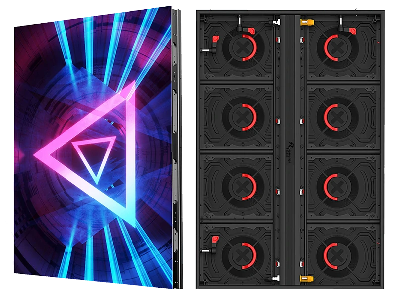
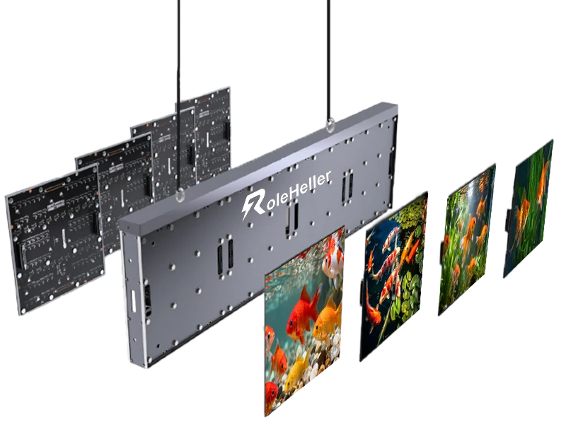
To evaluate hd led display manufacturers like an experienced hardware engineer, you must look inside the cabinet. A fine-pitch LED cabinet is an optoelectronic ecosystem comprising four primary layers:
+-------------------------------------------------------------------------+
|                    FINE-PITCH LED CABINET STACK                         |
+-------------------------------------------------------------------------+
| [Layer 1] Front Face: SMD Diodes / GOB Resin / COB Encapsulation        |
|-------------------------------------------------------------------------|
| [Layer 2] 6-to-8 Layer High-Tg FR4 PCB (2oz to 3oz Inner Copper Planes) |
|-------------------------------------------------------------------------|
| [Layer 3] High-PWM Constant-Current Driver ICs + Ghosting Removal Logic |
|-------------------------------------------------------------------------|
| [Layer 4] Precision CNC Die-Cast Aluminum or Magnesium Alloy Chassis    |
|-------------------------------------------------------------------------|
| [Layer 5] Dual-Rail Common Cathode Low-Noise Power Supply Units         |
+-------------------------------------------------------------------------+
Inside every surface-mount diode (SMD), hair-thin wires connect the semiconductor wafer to the external solder pins.
99.99% Pure Gold Bonding Wire: Premium manufacturers specify gold wire bonding (such as Nationstar RS series or Kinglight Gold-wire tier). Gold is chemically inert, resists thermal fatigue during frequent on/off cycles, and does not oxidize.
Copper / Alloy Wire Bonding: Lower-cost builders cut costs by substituting copper or copper-doped alloy wire. Copper oxidizes when microscopic amounts of moisture seep through epoxy casings, leading to open circuits, flickering driver channels, and dead pixels within eighteen months.
The driver silicon controls pulse-width modulation (PWM), refresh rate, and low-brightness color accuracy.
High-Tier PWM Drivers (e.g., Macroblock MBI5359, MBI5264, or Chipone ICND2065): These provide 16-bit to 18-bit true grayscale processing, refresh rates from 3,840Hz to 7,680Hz, and dedicated hardware circuits to eliminate ghosting and dark lines. In dark scenes, colors stay balanced without shifting red or green.
Entry-Level Dual-Latch Drivers: Low-end suppliers use legacy ICs operating at basic refresh rates (1,920Hz). When display brightness is lowered to comfortable indoor levels (100 to 200 nits), low-end chips suffer from severe color banding and visible scanning lines under video cameras.
Indoor video walls operate close to viewers. Running a hot display turns executive boardrooms into stuffy environments.
Common Anode (Traditional): A single 5.0V power rail feeds the Red, Green, and Blue dice. Because Red diodes only require 2.1V to 2.4V, the excess voltage converts into wasted heat.
Common Cathode (Modern Standard): Independent power rails feed 2.8V to Red dice and 3.8V to Green and Blue dice. This reduces overall power consumption by 25% to 35%, lowers the display surface temperature by 8°C to 12°C, and prevents thermal color drift across long operating sessions.
Choosing an HD display requires selecting the appropriate diode packaging technology for your installation environment. Here is how current packaging options compare:
| Packaging Technology | Typical Pitch Range | Surface Durability | Contrast & Black Levels | Field Repairability | Typical Cost Profile |
|---|---|---|---|---|---|
| Standard SMD | P1.2 – P2.5 | Low (Diodes exposed to physical impact) | Moderate (Matte black face masks) | Easy (Single-pixel hot-air rework) | Baseline 1.0x (Most Economical) |
| GOB (Glue-on-Board) | P1.2 – P1.8 | High (Transparent epoxy shield layer) | Good (Deep black epoxy finish) | Moderate (Requires specialized tools) | 1.15x – 1.25x |
| COB (Chip-on-Board) | P0.6 – P1.5 | High (Encapsulated wafer layer) | Exceptional (Seamless resin surface) | Challenging (Factory cleanroom return) | 1.40x – 1.80x |
| Micro LED (AM-TFT) | P0.4 – P0.9 | High (Direct active-matrix bond) | Reference Grade (Near-infinite contrast) | Tile-Swap Only (Cleanroom depot service) | 2.50x – 5.00+x |
If your display is mounted within reach of passersby—such as a university hallway, church lobby, or high-traffic corporate reception area—standard SMD modules are vulnerable to vacuum cleaner collisions, curious fingers, and cleaning crews. GOB applies a protective polyurethane resin layer across the module face, making it impact-resistant, dust-tight, and wipe-clean with a microfiber cloth.
When evaluating hd led display manufacturers, suppliers fall into distinct tiers based on production scale, technical capabilities, and warranty support:
+--------------------------------------------------------------------------+
|                  HD LED DISPLAY MANUFACTURING ECOSYSTEM                  |
+--------------------------------------------------------------------------+
|  [TIER 1: Public Brand Leaders] Leyard/Planar, Unilumin, Absen, Samsung  |
|   -> Strengths: Global local service, certified UL/ETL listings, AOI QA  |
|   -> Best For: Government control rooms, broadcast studios, flagships    |
|   -> Reality: 35% to 60% brand markup; long customization lead times     |
|--------------------------------------------------------------------------|
|  [TIER 2: Export OEM/ODM Engineering Fabs] CreateLED, Dicolor, Gloshine, |
|           Uniview LED, AOTO, Desay                                       |
|   -> Strengths: Flexible CAD design, direct factory BOM, high value      |
|   -> Best For: Corporate boardrooms, education, houses of worship        |
|   -> Reality: Exceptional build quality; requires strict BOM oversight   |
|--------------------------------------------------------------------------|
|  [TIER 3: Commodity Assemblers & White-Label Resellers]                  |
|   -> Strengths: Rock-bottom unit pricing, massive off-the-shelf stock    |
|   -> Best For: Short-term temporary displays, non-critical signs         |
|   -> Reality: Mixed diode bins, high heat, unreliable warranty coverage  |
+--------------------------------------------------------------------------+
Key Names: Leyard (Planar), Unilumin, Absen, Samsung Electronics, Sony.
Operating Reality: These companies operate expansive automated cleanrooms with integrated optical testing lines. They maintain regional repair centers and field engineers across North America and Europe.
Trade-Offs: Hardware pricing carries a significant brand premium. If your installation requires bespoke non-standard cabinet dimensions to fit inside existing architectural millwork, modifying their automated tooling lines can take months.
Key Names: CreateLED, Dicolor, Gloshine, Uniview LED, AOTO, Desay.
Operating Reality: These manufacturers serve the international AV integration and staging rental sectors. They run automated SMT lines equipped with Yamaha and Panasonic pick-and-place systems.
Trade-Offs: Sourcing managers must write precise technical specifications. Because Tier-2 plants offer multiple BOM configurations, leaving component details open allows factory sales desks to quote value-tier parts rather than their enterprise-grade packages.
Key Names: Unbranded white-label trading entities and low-cost domestic assemblers.
Operating Reality: They produce standard plastic-backed modules using low-grade copper-wire LEDs, generic driver chips, and basic power supplies.
Trade-Offs: Inconsistent diode binning leads to noticeable checkerboard color patches. Heat dissipation is poor, leading to premature diode failure and dropped scan lines within twelve to eighteen months.
| Technical Parameter | Tier-1 Enterprise Giants | Tier-2 Engineering OEM/ODM | Tier-3 Budget Assemblers |
|---|---|---|---|
| Typical Cost (P1.25 per m²) | $3,500 – $6,500+ USD | $1,800 – $2,800 USD | $900 – $1,300 USD |
| Primary LED Packaging | Nationstar Gold Wire / Nichia / Cree | Nationstar Gold or Copper / Kinglight | Generic Brand / Alloy Wire |
| Driver Silicon Standard | Macroblock MBI5359 / Chipone 2065 | Chipone ICND2153 / Macroblock 5153 | Unbranded Dual-Latch ICs |
| Refresh Rate | 3,840Hz – 7,680Hz | 3,840Hz | 1,920Hz |
| Cabinet Construction | CNC Die-Cast Magnesium / Aluminum | Die-Cast Aluminum Profile | Stamped Sheet Metal / Iron |
| Dimensional Tolerance | ≤ 0.05 mm (Zero visible seam) | ≤ 0.1 mm | ≥ 0.5 mm (Visible panel gaps) |
| Power Architecture | Common Cathode Energy-Saving Standard | Common Cathode or Hybrid High-Eff | Traditional 5.0V Common Anode |
| Certification Level | Full UL 48, ETL, FCC Class B, CE-EMC | Genuine ETL / UL / CE-EMC Listed | Self-declared CE marks only |
| Calibration Architecture | Pixel-by-pixel chromatic & luma files | Full-panel bin calibration archive | Uncalibrated / factory default |
| Expected Service Life | 80,000 to 100,000 Hours (Stable) | 60,000 to 80,000 Hours | 20,000 to 35,000 Hours |
When your display hardware arrives on site, precise installation practices determine final image quality. Because fine-pitch HD panels have zero bezels, mechanical misalignment of just 0.2 millimeters will produce visible black or bright seams.
                  SIX-STEP COMMISSIONING PROTOCOL

[Step 1: Structural Laser Leveling]  ===> Shoot rotary laser across base row
                 |
[Step 2: Base Frame Anchoring]       ===> Mount master bottom row; lock shims
                 |
[Step 3: Signal Loop Daisy-Chain]    ===> Primary Ethernet + Redundant Return
                 |
[Step 4: Common Cathode Power Bus]   ===> Balanced 3-phase AC distribution
                 |
[Step 5: Front-Magnetic Tile Snap]   ===> Center-out placement using vacuum tool
                 |
[Step 6: Optical Seam Calibration]   ===> Camera-assisted coefficient profiling
Level the Structural Base Frame: Before hanging any cabinets, level your bottom mounting rail with a precision rotary laser level. If your foundation bar is out of level by even 0.5mm across a four-meter span, that error will compound into severe panel overlap at the top corners.
Anchor Cabinets Sequentially: Bolt the center cabinets of your bottom row to the structural frame first, working outward toward the perimeters. Use the built-in precision alignment pins and adjust mechanical eccentric bolts to eliminate seam gaps before tightening structural anchors.
Route Signal Loops with Hardware Redundancy: Run your primary Gigabit Ethernet signal line from port 1 of your master video processor (such as a NovaStar MCTRL4K or Colorlight Z6 PRO) into the bottom-left cabinet, daisy-chaining across the wall. Then, run a backup return line from the final cabinet back to the processor's redundant port. If an intermediate network cable fails, the backup loop engages instantly without dropping video frames.
Distribute AC Power Evenly Across Phases: Calculate total cabinet current draw and split electrical circuits evenly across phases to prevent neutral-line overheating. Ensure dedicated ground cables bond directly from the cabinet chassis to the building electrical ground with a resistance reading under 4 ohms.
Mount Magnetic Modules from Center Outward: Use an electric vacuum-suction extraction tool to place magnetic modules onto cabinet chassis plates. Starting in the center and moving outward prevents accumulated physical tension across module edges.
Execute Camera-Assisted Seam Calibration: After powering on the display and allowing it to reach thermal equilibrium (around 45 minutes), use a DSLR calibration camera kit paired with NovaStar NovaLCT or Colorlight software to capture optical seam boundaries. The software detects micro-brightness variations at cabinet joints and applies localized edge-correction coefficients, producing a uniform visual canvas.
To help you navigate technical reviews during vendor negotiations, let us tackle the critical engineering questions that AV professionals encounter:
Moiré occurs when the physical grid pattern of individual LED diodes interferes with the pixel sensor grid of a digital camera. This optical interference creates distracting, wavy, rainbow-like artifacts across video recordings.
How to solve this:
Optical Diffusion Coatings: Choose GOB or COB modules treated with matte, anti-reflective micro-bead coatings that soften diode point-source edges.
Optical Anti-Moiré Filters: Apply a specialized resin film across the screen surface to blend adjacent light cones before camera sensors register them.
Camera Configuration: Adjust camera distance, focal length, and aperture to slightly defocus the LED plane while keeping on-camera presenters in sharp focus.
Most commercial LED screens look vivid when displaying full white or high-saturation primary colors. The real test occurs when displaying subtle shadows, dark gradients, or soft facial tones at low brightness levels (10% to 15% of peak output).
Cheaper driver ICs drop from 16-bit processing down to 10-bit or 8-bit depth at low drive currents, causing visible stepping rings, color banding, and red tint shifts in dark backgrounds.
To prevent this flaw, mandate driver ICs featuring Low-Grayscale Calibration and High-PWM bit depth (such as Macroblock MBI5359 or Chipone ICND2065). These driver chips maintain full 16-bit grayscale depth down to 0.05 nits, ensuring smooth tonal gradations in darkened viewing rooms.
Yes. Standard commercial LCD panels struggle in sunlit indoor spaces—such as glass atriums and retail storefronts—because their brightness tops out between 500 and 700 nits. High-quality fine-pitch LED displays can be calibrated to operate between 1,200 and 2,500 nits, cutting cleanly through afternoon solar glare without washing out dark content.
However, running high brightness in direct sunlight demands robust thermal planning. Ensure the manufacturer includes high-efficiency fanless power supplies, heat-dissipating aluminum chassis designs, and automated ambient light sensors that throttle brightness down to comfortable levels (150 to 300 nits) after sunset.
Never wire a production deposit based solely on a PDF quote and a polished corporate website. If your project involves a sizable commercial investment, follow this testing protocol during your pre-shipment factory audit:
+--------------------------------------------------------------------------+
|                  PRE-SHIPMENT FACTORY AUDIT PROTOCOL                     |
+--------------------------------------------------------------------------+
|  [ ] 1. Continuous 72-Hour Burn-In Testing                               |
|      - 24 hours full white balance at 100% brightness                    |
|      - 24 hours alternating pure Red, Green, and Blue test patterns      |
|      - 24 hours high-motion dynamic video playback                       |
|--------------------------------------------------------------------------|
|  [ ] 2. Low-Brightness Grayscale Verification                            |
|      - Dim screen to 5% brightness; display a 15% gray raster pattern    |
|      - Inspect for horizontal banding, red tint shifts, or dead pixels   |
|--------------------------------------------------------------------------|
|  [ ] 3. Camera Shutter Diagnostic Scan                                   |
|      - Film active screen using a DSLR at 1/1000s and 1/2000s shutter    |
|      - Confirm complete absence of black scan bars and flickering        |
|--------------------------------------------------------------------------|
|  [ ] 4. Physical Seam and Thermal Imaging Scan                           |
|      - Run FLIR thermal camera across cabinet rear; delta must be < 5°C  |
|      - Check panel seam tolerances with a 0.05mm feeler gauge            |
|--------------------------------------------------------------------------|
|  [ ] 5. Archive Calibration Data                                         |
|      - Verify chromatic and luminance bin files are stored on USB media  |
+--------------------------------------------------------------------------+
When reviewing video verification of your assembled display during burn-in testing, watch the screen when a solid white image is shown. A pure white raster reveals everything: if individual cabinets display subtle variations in color temperature—some leaning warm pink, others cool blue—the factory has mixed different diode binning batches. Reject that configuration immediately; every module on your screen must originate from the exact same diode wavelength and luminous intensity bin.
After spending years specifying, troubleshooting, and inspecting fine-pitch LED displays, here is my direct advice: you rarely need to pay a 60% brand premium to achieve clean, dependable HD visuals. But you cannot approach commercial LED walls like an off-the-shelf consumer television purchase where you simply select the cheapest option on a price comparison sheet.
The real risk when buying from overseas manufacturers is ambiguity. When a buyer simply asks for a "P1.25 indoor LED screen," factory sales desks assume the inquiry is driven strictly by low unit cost. They will quote thin circuit boards, copper-wire diodes, basic driver chips, and stamped iron frames because they assume price is the only metric that matters.
If you change the conversation from day one by providing an explicit technical specification:
Mandating 4-to-6 layer FR4 PCBs with 2oz copper planes.
Specifying Nationstar Gold-wire or Kinglight Gold-tier diodes.
Requiring Macroblock or Chipone high-PWM driver silicon.
Demanding CNC die-cast aluminum or magnesium alloy cabinets with ≤ 0.05 mm seam tolerances.
Requiring a 5% pre-calibrated spare module package from the master production run.
The manufacturer immediately recognizes your technical expectations. They will route your project to their senior engineering team, adhere strictly to your component parameters, and deliver a video wall that performs reliably throughout its operating life.
A practical engineering guideline is 1 meter of viewing distance per 1 millimeter of pixel pitch. For a P1.25 display, the minimum comfortable viewing distance is approximately 1.25 meters (around 4 feet). At this distance, an individual with normal 20/20 vision perceives the pixel matrix as a smooth, continuous image without spotting individual diode dots.
SMD solders individually packaged LED diodes directly onto the front surface of the PCB, using plastic louvers for mechanical protection. COB mounts bare semiconductor micro-wafers directly onto the board substrate, sealing the entire module surface under a continuous, protective optical resin layer. COB provides superior impact resistance, ultra-wide 170-degree viewing angles, and deeper black levels, but individual diode field repairs must be handled at dedicated cleanroom repair centers.
Seam prevention relies on CNC-machined die-cast aluminum or magnesium chassis built to tolerances within 0.05 millimeters. Cabinets incorporate precision stainless-steel alignment dowels and adjustable mechanical cam locks. Additionally, video processing software uses camera-assisted seam calibration to adjust pixel edge brightness, eliminating dark or bright boundaries between adjacent panels.
Common Cathode architecture routes separate, dedicated voltage lines to Red diodes (2.8V) and Green/Blue diodes (3.8V), rather than supplying a uniform 5.0V. Eliminating the need to dissipate excess Red voltage as heat reduces overall power consumption by up to 35% and drops display surface temperatures by 8°C to 12°C, preventing thermal color shifts and keeping indoor meeting spaces comfortable.
For installations in the United States and Canada, the entire assembled display system must carry an authentic UL 48 (Standard for Electric Signs) or ETL equivalent listing, along with FCC Part 15 Class A or Class B electromagnetic compliance. For the European Union, the display must carry certified CE-EMC, CE-LVD, and RoHS compliance reports issued by recognized testing bodies.
Yes. Modern fine-pitch indoor displays feature 100% front-serviceable architectures. LED modules are held firmly against the cabinet chassis by high-strength neodymium magnets. Technicians use an electric vacuum-suction extraction tool placed against the module face to safely pull panels forward, providing access to internal receiving cards, flat ribbon cables, and power supplies without requiring rear access corridors.
Your purchase contract should mandate an on-site spare parts package of at least 5% spare LED modules, 5% spare power supplies, 2% to 3% spare receiving cards, along with replacement ribbon data cables, magnetic extraction tools, and proprietary cabinet alignment hardware. Crucially, all spare modules must originate from the exact same diode production batch to ensure matching color temperature and luminance characteristics.
A commercial fine-pitch LED display built with gold-wire diodes and brand-name driver silicon has an expected operational lifespan of 80,000 to 100,000 hours (roughly 9 to 11 years of 24/7 operation) before brightness decays to 50% of its initial value. Running displays at moderate brightness levels (150 to 300 nits) in climate-controlled spaces prevents thermal stress and extends component lifespan.
The global market is led by NovaStar (using their COEX platform with MX-series processors and Armor/A10s Pro receiving cards) and Colorlight (using Z-series processors and 5G receiving cards). These platforms support low-latency 4K/8K video processing, 16-bit to 22-bit grayscale depth, HDR10/HLG color profiles, and automated camera-based seam calibration.
For standard die-cast aluminum cabinets using established pixel pitches (such as P1.25, P1.56, or P1.87), factory production generally takes 20 to 30 business days, which includes the mandatory 72-hour continuous burn-in testing cycle. Bespoke curved frames, custom architectural cabinet dimensions, or specialized high-density COB configurations typically require 35 to 50 business days for tooling and validation.