English
When sourcing from wholesale p3 led display manufacturers, the single most critical decision you will make comes down to locking the bill of materials before wiring a production deposit rather than negotiating purely on price per square meter. If you want the direct engineering verdict upfront: whether you are outfitting a church sanctuary, a municipal auditorium, a broadcast studio, or an event rental fleet, a reliable commercial-grade P3 (3.0mm or 3.076mm pixel pitch) display requires genuine Nationstar or Kinglight black-body SMD2121 LEDs with copper or gold bond wires, dedicated constant-current PWM driver silicon (such as the Macroblock MBI5153 or Chipone ICN2153) running at 1/16 scan, a 1.6mm 4-layer FR-4 TG170 printed circuit board with at least 1.5oz copper weight, precision CNC-machined die-cast aluminum 576mm × 576mm or 640mm × 480mm cabinets, and certified fanless industrial power supplies from Mean Well sized to no more than 70% continuous load. Bypassing trading intermediaries in favor of audited OEM/ODM factories in Shenzhen's Bao'an or Guangming districts that provide contractual single-bin diode lot matching and certified 72-hour continuous thermal burn-in is the only reliable way to protect your business from patchy color shifts, catastrophic driver IC burnouts, and crushing field service costs.
Below is an exhaustive, real-world engineering teardown, factory auditing framework, and procurement guide designed for AV integrators, display rental operators, and commercial signage contractors looking to source directly from Chinese manufacturing lines with complete technical certainty.
Picture this situation: your integration firm in London, Chicago, or Sydney lands a high-profile tender to supply a 6×3 meter indoor video wall for a corporate auditorium or a regional convention facility. You decide to bypass local distributors who mark up hardware by 35% to 50%, heading straight to overseas B2B export platforms to find wholesale manufacturers in southern China. Within forty-eight hours, your inbox is flooded with slick PDF brochures quoting complete P3 indoor display walls for as low as $380 per square meter.
The digital renders look stunning. The sales rep promises 1,200 nits brightness, 3840Hz refresh rate, Novastar processing, and a full three-year warranty. A single sample tile arrives via air courier, and it looks punchy and bright on your office test bench. You wire the 30% production deposit, wait six weeks for ocean freight, construct the ground-support trussing, and commission the video wall.
For the first four months, the display operates without complaint. Then summer arrives.
Under sustained daily operation in an air-conditioned room where ambient temperatures fluctuate between events, you notice faint color blocks appearing across adjacent panels. When showing a clean corporate white or light grey presentation slide, the screen looks like a patchwork quilt: some panels tint slightly yellow-green, while others shift toward magenta. By month seven, individual blue diodes begin to fail in random vertical streaks, and during live keynote speeches, attendees recording the speaker with their smartphones see dark rolling scan lines on their screens.
Suddenly, you are spending hundreds of dollars a visit on technician labor, swapping out receiver cards and pulling modules to replace driver chips, desperately trying to keep a client from withholding their final retention payment.
The screen did not fail by random bad luck. It failed because wholesale full color LED manufacturing in China is deeply stratified. In industrial centers like Shiyan, Fuyong, and Guangming, two cabinets that look identical from five feet away can have a 200% variance in raw component costs. When you understand where factory assemblers strip out build costs, you stop shopping for cheap price tags and start shopping for engineering specifications.
In an era where trade show marketing pushes sub-1.0mm micro-LEDs and ultra-fine narrow pixel pitch (NPP) panels, many buyers assume that 3mm is outdated. That assumption is an expensive commercial mistake. Indoor visual ergonomics follow predictable optical rules governed by the human eye's resolving acuity and viewer seating distances.
+-------------------------------------------------------------+
|                 Indoor P3 Optical Physics                   |
+-------------------------------------------------------------+
| Pixel Pitch        : 3.0mm (or 3.076mm on 320x160mm panels) |
| Pixel Density      : 111,111 pixels / m² (or 105,689 / m²)  |
| Minimum Viewing    : 3.0 meters (~10 feet)                  |
| Optimal Blend Point: 4.5 to 30 meters (~15 to 100 feet)     |
| Target Venues      : Churches, Auditoriums, Boardrooms, Bars|
+-------------------------------------------------------------+
When an audience sits in an auditorium, house of worship, or conference hall, the front row of seats is almost always situated at least three to four meters away from the stage. At a distance of three meters, the human eye with 20/20 vision cannot easily distinguish individual pixel clusters on a 3mm pitch display.
Installing a fine-pitch P1.5 or P1.8 display in that same venue doubles or triples your capital hardware expenditure, increases thermal density, and makes the screen far more vulnerable to physical impact damage, without delivering any perceptible visual benefit to attendees sitting ten feet away.
Because the surface-mount technology (SMT) packaging for P3 (predominantly SMD2121) has been refined over more than a decade, manufacturing yields in Guangdong are mature and high. That maturity makes P3 the most cost-effective, dependable workhorse in commercial AV. However, that exact same maturity also means that hundreds of small, low-tier workshops can buy cheap bare circuit boards, reject diode bins, and unbranded driver chips to assemble budget panels that compromise long-term operational stability.
To evaluate any quotation from an overseas manufacturer, you must strip the cabinet down into its foundational mechanical and electronic subsystems. When we are using these panels on commercial job sites, this is the internal architecture that separates industrial workhorses from budget toys:
+-------------------------------------------------------------+
|                  Anatomy of an Indoor P3 Module             |
+-------------------------------------------------------------+
| [Face Mask]     Matte Black Anti-Glare Polycarbonate Louvers|
| [LED Emitters]  SMD2121 Black-Body (Nationstar / Kinglight) |
| [PCB Substrate] 1.6mm 4-Layer FR-4 (TG170, ≥1.5oz Copper)   |
| [Driver Silicon]PWM Constant Current (MBI5153 / ICN2153)    |
| [Housing Frame] Reinforced Polycarbonate-ABS Structural Rim |
| [Terminals]     Gold-Plated 16-Pin IDC Data + VH4 5V DC Post|
+-------------------------------------------------------------+
The light-emitting diode represents between 40% and 55% of the total raw material cost of the panel. For indoor commercial environments, diode packaging directly dictates optical contrast:
Black-Body (Black-Face) SMD2121: The plastic housing surrounding the microscopic chip dies is molded from deep-black resin, paired with a matte-black face mask. This design absorbs ambient room lighting, delivering contrast ratios of 4,000:1 to 6,000:1. Dark video scenes, corporate presentations, and shadow details look rich, deep, and punchy.
White-Face SMD2121: White plastic surrounds the diodes. While white-face diodes produce higher raw luminous output at lower power, ambient room light bounces off the reflective white plastic. Contrast drops below 1,500:1, turning blacks and dark grays into a milky, washed-out haze.
Beyond the plastic housing, internal bond wires determine physical lifespan:
Gold Wire Bonding (Au): The premier standard for commercial reliability. Gold bond wires provide exceptional ductility, withstanding thousands of thermal expansion cycles without micro-cracking, and completely resist atmospheric oxidation.
Copper Wire Bonding (Cu): The industry standard for balanced commercial budgets. Copper provides strong electrical and thermal conductivity at an accessible price point, provided the packaging house maintains a strict inert nitrogen gas shield during ultrasonic bonding.
Alloy / Silver-Copper Wire: Found in budget wholesale panels. Silver-alloy wires are prone to atmospheric sulfurization and mechanical shear failure under repeated thermal cycles, leading to dead color channels (usually red or blue) within twelve to eighteen months.
The driver IC regulates the constant direct current flowing through each diode channel:
Basic Latching Shift Registers (generic 74HC595 derivatives or low-cost clones): These chips lack internal pulse-width modulation memory. They top out at refresh rates between 960Hz and 1,920Hz, show visible horizontal dark lines on smartphone cameras, and crush grayscale steps in dark scenes.
Dedicated PWM Constant Current Drivers (e.g., Macroblock MBI5153, MBI5252, or Chipone ICN2153, ICN2053): Essential for commercial signage, live events, and broadcast. These ICs deliver true 3840Hz refresh rates, smooth 14-bit to 16-bit grayscale depth, and built-in ghosting suppression circuits that eliminate trailing artifacts behind bright text.
A standard P3 module measuring 192mm × 192mm contains 4,096 individual RGB pixels (64 × 64 dots). A standard 320mm × 160mm module contains 5,408 pixels (104 × 52 dots on a 3.076mm pitch). Powering thousands of diodes requires careful trace design to prevent voltage drops.
Layer Count: Commercial P3 modules must use a 4-layer PCB. This separates DC power planes and ground planes from high-frequency clock and data traces, eliminating electromagnetic interference and image ghosting. Cheap modules use 2-layer boards that run power and data side-by-side, causing vertical line noise and localized heat zones.
Substrate Thickness & Tg: Insist on 1.6mm thickness with a glass transition temperature rating of TG150 or TG170. Flimsy 1.0mm or 1.2mm boards warp when heated, breaking the flat alignment between adjacent panels.
Copper Weight: Insist on at least 1.5oz (52μm) copper foil. Thin copper traces increase internal resistance, causing voltage drops that make center pixels visibly dimmer than edge pixels.
When evaluating factory quotes, use this matrix to decode component specifications and verify where your money is actually going:
| Subsystem Component | Tier 1: Commercial / Broadcast Grade | Tier 2: Standard Commercial Grade | Tier 3: Budget / High Risk |
|---|---|---|---|
| LED Packaging | Nationstar Black-Face SMD2121 (Gold Wire) | Kinglight Black-Face SMD2121 (Copper Wire) | Unbranded white-face, alloy bond wire |
| Driver Silicon | Macroblock MBI5153 / Chipone ICN2153 (PWM) | Chipone ICN2038S / Silan Micro | Generic 74HC595 shift registers |
| PCB Construction | 1.6mm 4-Layer FR-4, TG170, ≥1.5oz Copper | 1.6mm 2-Layer FR-4, TG140, 1.0oz Copper | 1.2mm 2-Layer Composite, 0.5oz Copper |
| Scan Mode Ratio | 1/16 Scan Rate (Cooler running, longer life) | 1/16 or 1/32 Scan Rate | 1/32 Scan Rate (Overdriven Current) |
| Native Refresh Rate | 3,840Hz (Zero camera rolling flicker) | 1,920Hz | 960Hz – 1,200Hz (Severe Camera Banding) |
| Power Terminals | Gold-Plated Phosphor Bronze VH4 Posts | Tin-Plated Brass Screw Terminals | Thin Steel-Plated Pins (Prone to Arcing) |
| Power Supplies | Mean Well UHP / LRS fanless slimline | Great Wall / Megmeet industrial | Unbranded open-frame power supply |
| Cabinet Precision | Die-Cast Aluminum CNC Machined (±0.05mm) | Die-Cast Standard Aluminum (±0.15mm) | Folded Sheet-Metal Iron Box (±0.50mm) |
A frequent question buyers face is: “Why does one wholesale factory quote a P3 screen at a noticeably lower price, only to mention in the fine print that it uses 1/32 scan instead of 1/16 scan?”
The scan ratio indicates how many rows of LEDs are multiplexed per constant-current driver IC channel.
1/16 Scan Module: Fewer rows per driver channel  --> Runs cooler, higher refresh, longer diode life
1/32 Scan Module: Double rows per driver channel --> Runs hotter, lower cost, accelerated color fade
In a 1/32 scan module, a single driver output channel multiplexes sequentially across thirty-two separate rows. To achieve an indoor brightness of 800 to 1,000 nits, the diodes must be driven with intense, high-current pulses for brief duty cycles. This spikes the internal junction temperature, accelerating lumen degradation and color shifts.
A 1/16 scan module uses twice as many driver ICs across the board. Because each driver channel manages half as many rows, the duty cycle is longer, allowing the LEDs to produce equal or greater brightness with lower peak forward currents. The module runs noticeably cooler, draws power more evenly, and maintains stable color rendering over several years of continuous operation.
For permanent commercial installations running eight or more hours a day, 1/16 scan is the baseline engineering choice. Reserve 1/32 scan only for temporary, low-budget setups where long-term color fidelity is secondary.
A video wall is only as flat as the underlying chassis supporting the modules. Even tiny misalignments between adjacent panels create visible black seams or bright edges that break visual immersion.
Sheet-Metal Enclosure:      Manual welds, thermal warping, ±0.50mm tolerances, visible seams
Die-Cast Aluminum Frame:    CNC milled, alignment pins, ±0.05mm tolerances, seamless video surface
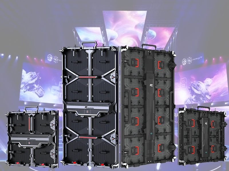
For commercial indoor projects, specify die-cast cabinets—commonly sized at 576mm × 576mm (housing nine 192mm × 192mm modules in a 3×3 grid) or 640mm × 480mm (housing six 320mm × 160mm modules in a 4:3 native ratio).
Dimensional Precision: Die-cast frames are cast in high-tonnage steel molds and finished on multi-axis CNC machines, maintaining tolerances within ±0.05mm. Adjacent cabinets lock together flush, eliminating visible seams.
Passive Heat Sinking: Aluminum and magnesium alloys conduct heat away from the rear of the modules, keeping internal electronics cool without requiring noisy fans.
Structural Weight: A fully loaded die-cast 576mm × 576mm cabinet weighs roughly 7.5kg to 8.5kg, making wall-bracket installation straightforward without structural steel reinforcement.
Standard iron sheet-metal boxes are cut, bent, and spot-welded by hand. Welded joints naturally pull and warp as they cool, leading to edge variances of ±0.5mm or more. While acceptable for coarse outdoor billboards viewed from 50 feet away, a half-millimeter gap on an indoor P3 display is immediately obvious to viewers.
Choosing between P2, P2.5, P3, and P4 requires balancing viewing distances, native video aspect ratios, and total hardware investments:
| Engineering Parameter | Indoor P2.0 | Indoor P2.5 | Indoor P3.0 | Indoor P4.0 |
|---|---|---|---|---|
| Pixel Density (dots/m²) | 250,000 | 160,000 | 111,111 | 62,500 |
| Minimum Viewing Distance | 2.0 meters (~6.5 ft) | 2.5 meters (~8.0 ft) | 3.0 meters (~10.0 ft) | 4.0 meters (~13.0 ft) |
| Standard Module Size | 320mm × 160mm | 320mm × 160mm | 192×192mm / 320×160mm | 320mm × 160mm / 256×128mm |
| Matching Cabinet Size | 640mm × 480mm | 640mm × 480mm | 576×576mm / 640×480mm | 640mm × 480mm / 512×512mm |
| Peak Power Draw (per m²) | ~650W – 750W | ~550W – 650W | ~450W – 550W | ~400W – 500W |
| Average Power Draw (m²) | ~220W – 260W | ~180W – 220W | ~150W – 190W | ~130W – 170W |
| Relative Cost Factor | 135% – 150% | 115% – 125% | 100% (Baseline) | 75% – 85% |
| Primary Venues | Broadcast studios, executive suites | Conference rooms, auditoriums | Churches, lecture halls, clubs | Large arenas, high-hung banners |
P3 strikes a practical balance. A 16:9 Full HD (1920 × 1080) video wall built with P3 panels measures roughly 5.76 meters wide by 3.24 meters tall (18.9 ft × 10.6 ft)—an impressive scale for a church altar or hotel ballroom that fills an audience's field of view without unnecessary hardware costs.
Most of the world's LED video display hardware originates in southern China's Guangdong province. Knowing how regional ecosystems operate helps you identify genuine manufacturers:
                      +---------------------------------------+
                      |      Guangdong LED Display Ecosystem  |
                      +---------------------------------------+
                                          |
            +-----------------------------+-----------------------------+
            |                                                           |
+-----------------------+                                   +-----------------------+
|  Shenzhen (Shiyan /   |                                   |  Huizhou & Dongguan   |
|  Bao'an / Guangming)  |                                   |  Industrial Campuses  |
+-----------------------+                                   +-----------------------+
| Core R&D, rapid SMT,  |                                   | Large automated lines,|
| custom engineering,   |                                   | container-scale runs, |
| export operations     |                                   | lower land overhead   |
+-----------------------+                                   +-----------------------+
Shenzhen is the center of global LED display engineering.
The Landscape: Districts like Shiyan and Fuyong host specialized component makers, controller developers (such as Novastar and Colorlight), optical test labs, and high-speed SMT assembly plants.
The Trap: The dense supplier network allows trading intermediaries to pose as major manufacturers. These operations rent sales offices, buy loose modules from small assemblers, screw them into stock cabinets in back rooms, and market them under proprietary names. Always verify that a supplier operates automated SMT lines with high-speed equipment from brands like Yamaha, Fuji, or Panasonic.
Over the past decade, established manufacturers built large, automated industrial campuses in neighboring Huizhou and Dongguan to scale operations beyond Shenzhen's rising real estate costs.
The Landscape: These plants focus on automated production with cleanroom environments and strict ISO9001 quality controls.
Trade-Offs: They offer reliable batch consistency for multi-container shipments, but minimum order quantities (MOQs) are higher and engineering flexibility for custom frame designs is limited.
Before signing a purchase contract, work through these three core engineering questions with your technical team:
LED manufacturing relies on semiconductor wafers that naturally drift in electrical and optical performance across production runs. Packaging houses sort finished diodes into tight bins based on three criteria:
Dominant Wavelength (nm): Determines the exact hue of red, green, and blue.
Luminous Intensity (mcd): Determines brightness under a given current.
Forward Voltage (Vf): Dictates electrical characteristics.
Even if you reorder the exact same model number from the same factory two years later, the replacement modules will come from a different diode wafer lot. If plugged directly into an existing screen, they will stand out as mismatched color patches.
The Solution:
Order an upfront spare parts allowance of at least 5% to 8% taken directly from the same production binning run.
Specify receiving cards that support onboard calibration storage (such as Novastar Armor or A-series cards). This stores sub-pixel chroma and luminance calibration data directly on the module's EEPROM, allowing replacement panels to blend into the surrounding display automatically.
Rear-Service Cabinets: These feature access doors on the back of the enclosure. Technicians must stand behind the display to service modules, power supplies, or receiving cards. This setup requires at least 60cm to 80cm of clear service space behind the screen, consuming valuable room area.
Front-Service Cabinets: Modules attach to the chassis using magnetic pillars. Technicians remove individual modules in seconds using a handheld vacuum suction tool directly from the front face. Power supplies and receiving cards can also be serviced from the front, allowing the entire video wall to be mounted directly against an existing wall.
Rear Service: Requires dedicated walk-in corridor behind screen (eats square footage)
Front Service: Magnetic module mounting; zero rear clearance needed; wall-hugging installation
Indoor P3 modules draw significant direct current along the 5V power bus when displaying pure white at peak output.
If internal DC power wiring uses undersized copper or loose screw terminal blocks, the voltage will drop from 5.0V at the power supply terminal down to 4.4V or lower by the time it reaches the end of the module chain.
Red diodes have a lower forward voltage threshold (~1.9V to 2.1V) compared to blue and green diodes (~2.9V to 3.2V). When line voltage drops significantly, blue and green channels starve for headroom first, leaving corner pixels with a noticeable pink or reddish tint.
Require the factory to supply pure copper UL1015 14AWG or 16AWG DC power leads and route power in a star configuration rather than daisy-chaining more than two modules together.
Never release final payment based purely on marketing photos or PDF test reports. Implement this structured five-step pre-shipment audit when inspecting your production run:
+---------------------------------------------------------------+
|               Factory Quality Inspection Protocol             |
+---------------------------------------------------------------+
| Step 1: Solder Fillet Teardown & PCB Inspection               |
| Step 2: Seam Flatness & Alignment Jig Verification           |
| Step 3: 72-Hour Continuous Dynamic Thermal Aging Run          |
| Step 4: FLIR Thermal Imaging Scan for IC Hotspots             |
| Step 5: Low-Brightness Grayscale Linearity & Uniformity Check |
+---------------------------------------------------------------+
Select three sample modules at random from the finished production lot.
Inspect the surface-mount solder joints under a 20x inspection microscope or jeweler's loupe. Solder fillets around the SMD diode pads and driver IC pins must be smooth, concave, and shiny, showing proper wetting without solder bridging or balls.
Check the board edge to confirm the 4-layer construction and verify clear FR-4 material markings.
Have technicians assemble a 3×3 cabinet array on a leveled precision platform.
Run your fingertips across the horizontal and vertical seams between adjacent cabinets. The surface transition should feel completely smooth, with seam gaps measuring less than 0.05mm.
If you can catch your fingernail on the edge of a module or slide a standard 0.2mm automotive feeler gauge between cabinets, the cabinet CNC milling was poorly calibrated and the wall will show visible seams once mounted.
Demand a documented 72-hour burn-in process on the factory testing wall:
First 24 Hours: Cycle through pure primary colors (Red, Green, Blue) at maximum brightness to trigger infant mortality in marginal diodes.
Second 24 Hours: Run continuous 100% full-white balance to stress the power distribution traces and driver IC thermal dissipation vias.
Final 24 Hours: Play high-dynamic-range video loops with rapid black-to-white contrast shifts to test signal buffering and refresh stability.
While the test wall displays full white at 100% brightness, walk the display with a calibrated FLIR thermal camera.
In an ambient room temperature of 25°C, healthy P3 modules should operate between 38°C and 48°C across the rear board surface.
If individual driver ICs or localized power traces glow at 65°C or higher, the PCB copper layout is unbalanced or the driver chips are being overdriven, which points to premature failure down the road.
Indoor displays rarely run at 100% brightness; in a church or conference room, they typically operate between 20% and 40% output to prevent eye fatigue.
Dim the display down to 15% brightness and inspect a 16-step gray ramp test pattern.
Look for grayscale banding, pink color tinting in dark grays, or flickering in the lowest steps. High-performance driver ICs maintain smooth, neutral-gray transitions even at very low output levels.
A reliable video wall depends on the external hardware supporting it behind the scenes:
Never pair high-spec P3 modules with unbranded power supplies.
Standardize on recognized industrial units like Mean Well (specifically the fanless, slimline UHP-200-5 or LRS-350-5 series) or certified commercial equivalents from Great Wall.
Size your power supplies so they operate at no more than 70% to 75% of their rated continuous capacity. Operating power supplies near their maximum ceiling generates excessive heat, shortens capacitor life, and introduces high-frequency switching noise into the 5V power bus, which can show up as faint horizontal lines across your video feed.
Cabinet Power Calculation Rule:
Total Module Peak Watts = (Module Count x Max Wattage Draw)
Required Power Supply Rating = Total Module Peak Watts / 0.70
Rely on established control platforms like Novastar (such as their TB-series multimedia players for standalone displays or COEX/VX-series processors for multi-input switching) or Colorlight.
Use shielded CAT6 network cabling with high-quality RJ45 connectors for internal cabinet data loops to prevent electromagnetic interference from nearby building systems.
When managing LED display installations over the long run, practical realities take precedence over marketing claims.
Avoid getting caught up in brightness races for indoor screens. A supplier boasting 1,500 nits on an indoor P3 display is not offering advanced technology; they are simply pushing standard diodes with excessive forward current. In a normal commercial interior, running an LED screen at 1,500 nits causes immediate eye strain for viewers. A calibrated, stable 600 to 800 nits paired with high optical contrast, a matte black mask, and deep black resin will look richer and outlast an overdriven screen by years.
Make sure your purchase agreement explicitly lists every critical component model down to the part number. Never accept vague phrasing like "Nationstar or equivalent" or "high-refresh Taiwan driver IC." Your purchase order should clearly specify: Nationstar Copper-Wire SMD2121 Black-Body LEDs, Macroblock MBI5153 Driver IC, 1.6mm 4-Layer TG170 FR-4 PCB, 1/16 Scan, and Mean Well UHP-200-5 power supplies. Having exact component specifications on paper gives you contractual protection if substitutions occur during production.
Finally, protect your investment by keeping spare parts on hand from day one. For an installation of 200 modules, always order at least 10 complete spare modules from the exact same diode wafer bin, 200 loose matching LEDs on tape-and-reel, 20 driver ICs, two spare receiver cards, and plenty of spare ribbon cables and power leads. Having those exact-match parts in your local storage means you can resolve panel damage in minutes without waiting weeks for an overseas replacement that might not match your screen's color profile.
Hope this breakdown helps you evaluate wholesale factory quotes with confidence and build commercial video walls that perform reliably for years to come.
"P3" designates a center-to-center pixel pitch of 3.0 millimeters (or 3.076mm on standard 320mm × 160mm modules). At a 3.0mm pitch, each square meter contains exactly 111,111 pixels. On a standard 192mm × 192mm module, this equates to 64 pixels horizontally by 64 pixels vertically, providing 4,096 pixels per module.
The standard rule of thumb for human visual acuity is approximately one meter of viewing distance per millimeter of pixel pitch. For an indoor P3 display, comfortable viewing begins at approximately 3.0 meters (around 10 feet). Viewers closer than three meters may begin to resolve individual pixel dots, while viewers beyond five to six meters perceive a smooth, continuous image.
Tier-1 commercial manufacturers primarily specify Nationstar (particularly their copper-wire and gold-wire commercial series) and Kinglight. Secondary commercial options include Honglitronic and Mulinsen (MLS). Unbranded white-box diodes should be avoided for permanent installations due to inconsistent color binning and high early failure rates.
The scan ratio indicates how many rows of LEDs are multiplexed per constant-current driver IC channel. A 1/16 scan module uses twice as many driver ICs as a 1/32 scan module. This design delivers higher refresh rates, reduces thermal stress on individual diodes, and extends the operational lifespan of the panel, making it the preferred choice for commercial installations.
Price differences reflect the underlying bill of materials. An inexpensive panel typically uses a 2-layer composite PCB, generic shift registers without PWM, alloy-wire white-face diodes, and folded sheet-metal cabinets. A commercial-grade display uses a 4-layer TG170 fiberglass PCB, branded PWM driver ICs (like Macroblock or Chipone), copper or gold-wire black-face LEDs, and CNC-machined die-cast aluminum cabinets.
Yes, provided you specify front-service magnetic modules and compatible cabinets. Technicians can remove individual modules in seconds using a handheld vacuum suction tool directly from the front face, allowing the screen to be mounted flush against a wall without requiring a dedicated rear service corridor.
The two most widely used formats are 576mm × 576mm die-cast aluminum cabinets (housing nine 192mm × 192mm modules in a 3×3 grid) and 640mm × 480mm die-cast cabinets (housing six 320mm × 160mm modules in a 4:3 native ratio). Both formats allow installers to build standard 16:9 widescreen video walls matching standard HD and 4K resolutions.
Request an unscheduled live video walkthrough during normal working hours in Shenzhen. Ask to see the automated SMT surface-mount lines (checking for equipment from brands like Yamaha or Panasonic), the optical test benches, and the active 72-hour burn-in wall. Trading intermediaries will usually offer pre-recorded promotional videos or show only sales offices and showrooms.
Specify a native refresh rate of at least 3,840Hz powered by dedicated PWM constant-current driver ICs. This refresh rate ensures that video playback remains smooth and prevents rolling scan lines or flicker when the display is photographed or recorded with modern smartphones and video cameras.
For North American installations, specify FCC Part 15 Class A for electromagnetic compatibility, along with cabinet-level safety certifications to UL 48 or ETL, with internal power supplies certified to UL 62368-1. For European installations, require third-party accredited lab test reports for CE-EMC (EN 55032/EN 55035), CE-LVD (EN 62368-1), and full RoHS compliance covering hazardous substance restrictions.
.jpg "China P2.9 Indoor LED Video Wall Manufacturers: Who Delivers?")