 English
Yes, you can buy directly from DIY LED display manufacturers and upstream component fabricators, but you will not find them packaged like an Ikea desk with step-by-step cartoon manuals. What you are actually buying is raw industrial hardware: bare SMD LED modules, Novastar receiving cards, 5V switching power supplies, and hub ribbon cables sourced straight from OEM fabrication lines. Sourcing this hardware directly cuts total project costs by 40% to 65% compared to commercial AV integrators, but it shifts the entire burden of calibration, batch binning, power load calculation, and structural alignment squarely onto your workbench.
Have you ever looked at a $30,000 quote for a modest 130-inch church or sim-racing video wall and thought, "Wait, isn't this basically just an array of circuit boards, a few Mean Well power bricks, and an aluminum frame?"
You are not wrong. That is exactly what commercial video walls are under their sleek powder-coated bezels. But the term diy led display manufacturers is widely misunderstood by folks entering this space. There is almost no single factory with a consumer website called "The DIY Screen Co." Instead, sourcing a custom LED wall means navigating an ecosystem of component fabricators, module packagers, and controller engineers. If you know how that supply chain operates, what questions to ask factory sales reps, and how to dodge the dreaded "mixed batch diode" curse, you can assemble a broadcast-grade display in your own garage or studio for a fraction of retail.
When someone talks about buying from LED display manufacturers, they usually picture a single company that smelts the metal, solders the silicon, and boxes up a finished display. In real life, the LED video wall market is heavily segmented. If you contact an industrial giant like Absen, Leyard, or Unilumin, their sales department will politely redirect you to an authorized local distributor who will mark up the hardware by 300% to cover installation labor and service warranties.
To build a display yourself, you deal with four distinct tiers of manufacturers:
The Diode Packaging Giants: Companies like Nationstar and Kinglight package raw RGB LED chips into surface-mount diodes (such as SMD 1515, SMD 2121, or SMD 1010). Semiconductor firms like Macroblock (MBI) and Chipone manufacture the constant-current driver ICs on the back of each board.
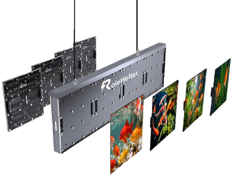
The Bare Module Fabricators: This is where DIYers spend most of their budget. Factories like Qiangli Jucai, Meiyad, and specialized OEM production lines in China stamp out the raw PCB modules—typically 320mm × 160mm standard boards containing the diodes, drive chips, plastic louver masks, and magnetic mounting posts.
The Control System Manufacturers: Novastar is the dominant industry standard, with Colorlight and Linsn holding secondary market share. They produce the sending boxes (like the MSD300 or VX400 video processors) and the receiving cards (like the MRV208 or DH7516) that decode video signals into row-and-column data for the driver ICs.
The Power Supply Manufacturers: Mean Well is the gold standard here. Powering bare modules requires clean 5V direct current, often pulling 30 to 40 amps per square foot at peak white brightness. Never cut corners with generic, unbranded power supplies unless you want high-frequency coil whine and thermal shutdowns halfway through your first screening.
Before pulling out your credit card, you need to decide how deep into the component weeds you want to go. Buying loose PCB boards is very different from buying pre-assembled die-cast aluminum rental cabinets.
| Sourcing Route | Average Cost ($ / m²) | Minimum Order (MOQ) | Assembly Complexity | Factory Support & Spares | Best Suited For |
|---|---|---|---|---|---|
| Direct Shenzhen Module OEM (Qiangli, Meiyad, custom Alibaba OEM) | $280 – $650 | Often 10–20 modules (~0.5 m²) | High: Custom frame, magnetic mounts, custom DC wiring, config files | Raw components only; you must order 10–15% spare modules | Makers, budget-strapped venues, custom aspect ratios |
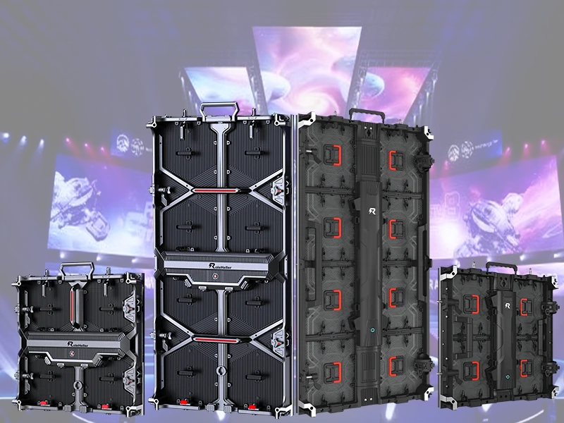
| Pre-Fabricated Die-Cast Cabinets (Gloshine, Dvon, OEM rental lines) | $700 – $1,400 | 2–4 cabinets (~0.5 to 1 m²) | Moderate: Quick-lock frames, plug-and-play internal power/data | Good; includes cabinet wiring harnesses, factory .rcfgx files | Sim-rigs, mobile event rigs, permanent square video walls |
| Western White-Label Resellers (Domestic boutique kit sellers) | $1,500 – $3,200 | Single units | Low: Detailed English manuals, pre-configured software | Local warranty, fast RMA, English-speaking phone support | Church tech teams wanting a safety net, corporate lobbies |
| Used Touring/Rental Market (GearSource, eBay, local production liquidation) | $400 – $900 | Whatever is left in the flight case | Moderate to High: Fixing dead pixels, tracking down old firmware | None; dependent on finding matching retired inventory | Enthusiasts who know how to solder and test with a multimeter |
Many builders get overexcited, wire money across the Pacific, and receive a wooden crate full of modules that look great on paper but fail under real-world conditions. When speaking with factory reps, specify these engineering parameters in writing:
Diode Brand and Wire Bonding: Always ask for Nationstar gold-wire or high-grade copper-wire LEDs if your budget allows. Cheaper Kinglight or unbranded white-label diodes run hotter, have higher dead-pixel failure rates out of the box, and shift color temperature as they age.
Driver IC Type and Refresh Rate: If you plan to point a camera at your screen (such as in a home virtual production studio or church broadcast), you need high-refresh driver ICs like the Macroblock MBI5153 or Chipone ICN2153. Demand a refresh rate of 3,840 Hz or higher. Cheap 1,920 Hz double-latch modules produce dark scan lines and moiré flutter whenever a phone or video camera records them.
The Magic File (.rcfg or .rcfgx): This is where most first-time DIYers hit a brick wall. Every module uses a specific scan rate (like 1/16 scan, 1/32 scan) and a custom pin-out layout. If the factory does not send you the exact configuration file for that specific production run, you will spend days using trial-and-error tools inside NovaLCT trying to decode the multiplexing. Get the .rcfgx file sent to your email before the crate ships.
The "One-Batch" Rule (Wavelength & Chroma Binning): LED diodes are grown on silicon wafers and grouped into "bins" based on their exact microscopic color spectrum and brightness output. If a factory sends you 40 modules from Batch A and 10 modules from Batch B, your screen will look like a patchwork quilt of mismatched whites and uneven greens. Never piece together a screen from multiple separate orders. Buy all the modules you need for the display plus a mandatory 10% to 15% spare allowance from a single, unified production lot.
When evaluating factory quotes, specs on paper rarely match field conditions. Here is what to watch out for:
| Spec on Factory Datasheet | What It Actually Means in Practice | Minimum Target for Quality DIY | Dangerous Red Flag |
|---|---|---|---|
| Brightness (Nits / cd/m²) | Indoor modules need 500–800 nits. More is not better indoors; running 1,500 nits in a basement will burn your retinas. | 600 – 800 nits (adjustable via software down to 15%) | Fixed-brightness modules that lose grayscale detail when dimmed |
| Grayscale Depth | Determines how smooth dark shadows and color gradients look without digital banding. | 14-bit minimum; 16-bit preferred for HDR or video games | 10-bit or 12-bit (muddy blacks, severe contouring in dark scenes) |
| PCB Layer Count | Thicker PCBs dissipate heat evenly away from the driver chips to prevent thermal solder cracks. | 4-Layer PCB construction | Ultra-thin 2-layer PCBs (they bow under magnetic tension and overheat) |
| Scan Mode | The multiplexing ratio of the driver chips. Lower ratios mean higher stability and brighter output per diode. | 1/16 scan for P2.5; 1/26 to 1/32 scan for fine-pitch P1.5/P1.8 | Unusually high scan rates paired with rock-bottom price tags |
| Connector Quality | 16-pin ribbon cable header pins and 5V DC screw terminals. | Gold-flashed header pins and brass power posts | Flimsy tin pins that bend upon first insertion; stripped screw threads |
Once the boxes arrive, the real work starts. A video wall is not just an array of pixels; it is an industrial electrical load mounted to a physical plane where tolerances are measured in fractions of a millimeter.
Let's look at the electrical reality. Suppose you are building a modest P2.5 display that is 8 modules wide by 4 modules high (a total of 32 modules, measuring roughly 2.56 meters by 0.64 meters).
A typical indoor P2.5 module pulls roughly 4.5 to 5.5 amps at 5V DC when displaying full, 100% white test patterns.
32 modules × 5 amps = 160 amps at 5V DC at absolute peak white.
In wattage, that is: 160 A × 5 V = 800 Watts.
Because typical video content has an average picture level (APL) of around 30% to 40%, your average draw will hover closer to 250 to 350 Watts. But you must wire your power supplies for peak load, not average load.
If you run a standard Mean Well LRS-200-5 (5V, 40A output), you will need: 160 A / 40 A = 4 power supplies.
A common beginner mistake is daisy-chaining too many modules together on one power lead. 5V direct current suffers from brutal voltage drops over thin wire. If voltage drops below 4.5V at the end of a chain, red diodes start failing first, producing sickly greenish-blue patches. Never run more than two to three modules from a single 16 AWG power wire drop.
A standard P2.5 module has pixels spaced just 2.5 millimeters apart from center to center. If two adjacent modules are out of alignment by even 0.3 millimeters, you will see an obvious dark gap or an ugly bright seam when viewing the wall from an angle.
Commercial rental cabinets are CNC-machined from cast aluminum blocks to guarantee dead-flat seams. For a DIY build using loose modules, you cannot simply screw them onto a sheet of plywood—wood warps with humidity, and your seams will split apart within a week.
The best approach is to build a grid using 2020 or 2040 extruded aluminum profile rails. The modules come with M3 or M4 magnetic mounting lugs threaded into their plastic backings. You attach thin steel mounting plates or precision flat bars across your extruded aluminum frame, and the modules snap into place magnetically. This lets you slide them into micro-alignment using a razor blade or feeler gauge before locking down your back brackets.
Hardware is only half the battle. Once your cabinet is framed and your power supplies are buzzing quietly, you will plug an Ethernet cable from your Novastar sending box (like a basic MSD300 or modern VX400) into the first receiving card.
Here is the setup path you will follow inside NovaLCT (Novastar's configuration software):
Log into Advanced User Mode: Open NovaLCT, click the user login dropdown, select "Advanced Synchronous System User," and enter the default password (admin or 666666).
Screen Configuration: Under the "Screen Configuration" panel, choose your COM port, navigate to the "Receiving Card" tab, and hit "Load from File." This is where you feed the software that .rcfgx file you demanded from your factory sales rep.
Send to Hardware: Click "Send to HW," then click "Save." If the configuration matches your modules, the scrambled static on your display will instantly snap into a clean, solid image or desktop mirror.
Cabinet Mapping: Go to the "Screen Connection" tab. Here, you tell the controller how your data cable snakes through the back of the wall. For example, if your CAT6 cable runs from the bottom-left cabinet, travels up through Column 1, hops over to Column 2, and snakes down to the bottom, you click the corresponding grid pattern in software. One wrong click here and half your video feed will render upside down or backwards.
You can drive one or two small 64×64 hub75 modules off an ESP32 or a Raspberry Pi using Henner Zeller's popular open-source rpi-rgb-led-matrix library. It works great for a desktop retro clock or a single low-res art piece. But do not try to build a 4K home theater or church video wall that way. Driving thousands of high-speed PWM channels across a multi-panel matrix requires dedicated FPGA processing. Real display systems rely on dedicated receiving cards to manage precise timing, color calibration curves, and frame sync without dropping frames or tearing.
COB is fascinating because the bare LED chips are bonded directly to the PCB and encapsulated in a smooth protective resin layer. It is virtually immune to physical impact, dust, and moisture. But for the DIY community, COB is a double-edged sword. If an individual diode fails on an SMD module, you can pull out a hot air rework station, desolder the 1515 SMD diode, and solder down a fresh spare in ten minutes. If a diode fails on a COB panel, repairing it at home without specialized resin molds and micro-soldering gear is almost impossible. Stick to SMD or GOB (Glue-on-Board) if you want serviceable hardware.
Use the standard 8-foot-per-millimeter rule. Take your pixel pitch in millimeters and multiply it by roughly 8 to find the minimum distance in feet where the human eye stops seeing individual dots:
P1.25 / P1.5: Sharp at 10 to 12 feet. Perfect for home theaters and small sim rigs, but extremely fragile and expensive.
P2.0 / P2.5: The sweet spot for DIY. Sharp at 16 to 20 feet. Forgiving to handle, affordable, and easy to align with magnetic mounts.
P3.91 / P4.81: The rental and stage standard. Sharp at 30+ feet. Great for outdoor movie screens, bands, and backdrops where viewers sit further back.
If you calculate your time at $75 an hour, building your own LED display will never be cheaper than buying a pre-integrated system or a consumer 98-inch OLED television.
You will cut your fingers on aluminum extrusions. You will spend hours chasing down a flickering seam caused by a loose ground wire. You will stare blankly at Chinese firmware error codes in NovaLCT at 2:00 AM wondering why receiving card #4 refuses to store its network address.
The real reward of working directly with DIY LED display manufacturers isn't just saving cash; it is complete ownership over your hardware. When a power supply fails three years down the line, you don't wait three weeks for an integrator's service technician to charge you $250 an hour to look at it. You walk over to your spare parts bin, swap a $25 Mean Well brick or a magnetic module in five minutes, and keep running. You built it, you know every trace on the board, and you control the ecosystem.
Most bare-module factories on platforms like Alibaba or direct factory portals set their MOQ around 10 to 20 loose modules, which translates to roughly half a square meter of screen area. For complete aluminum cabinets, MOQs generally sit at 2 to 4 units. If you explain that you are building an evaluation prototype for a larger deployment, sales reps will usually let you buy single-unit sample batches, though you may pay a modest 10% to 15% sample fee.
For a dependable indoor P2.5 display using genuine Nationstar diodes, high-refresh driver ICs, Novastar receiving cards, and Mean Well power supplies, expect to spend roughly $450 to $700 per square meter on core electronics. Custom aluminum structural framing, mounting brackets, primary AC circuit breakers, and video cabling typically add another $100 to $200 per square meter, bringing the total DIY cost to around $550 to $900 per square meter.
LEDs are manufactured in specific production runs called "bins," which have subtle, microscopic variations in color wavelength and forward voltage. If an LED diode burns out next year and you buy a replacement module from a future production lot, the white balance and tint will not match your existing screen, leaving a visible off-color patch. Always order at least 10% to 15% spare modules, extra ribbon cables, and spare driver ICs from the exact same manufacturing batch as your main screen.
Yes, provided your electrical calculations account for peak load. In North America, a standard 120V household circuit with a 15-amp breaker can safely deliver continuous power up to roughly 1,440 Watts (the 80% rule). In Europe, a standard 230V 16-amp circuit can handle up to 3,680 Watts. A medium-sized 130-inch indoor P2.5 display pulling an average of 400 to 600 Watts runs comfortably on a single standard wall circuit, though you should split very large displays across multiple dedicated breakers to handle startup inrush current.
Indoor modules prioritize tight pixel pitches (P1.2 to P2.5), high refresh rates, and subtle grayscale rendering at lower brightness levels (500 to 800 nits). Outdoor modules use larger pitches (P3.9 to P10), feature heavy IP65 waterproof silicone potting over the circuit traces, include protective UV-stabilized rubber louver masks, and output extreme brightness levels (5,000 to 8,000+ nits) to overpower direct sunlight. Never use indoor modules outdoors, as humidity, condensation, and sunlight will destroy them rapidly.
At a minimum, you need a high-quality digital multimeter for checking DC voltage drops and verifying polarity, a precision wire stripper and ratcheting ferrule crimper for secure terminal wiring, a calibrated magnetic level or laser line level, metric hex drivers (specifically M3 and M4), a hot air rework station with solder flux for replacing damaged diodes, and a Windows laptop with an Ethernet port to run the Novastar NovaLCT configuration utility.
NovaLCT—the primary configuration tool used to map receiving cards, adjust driver IC scan rates, and configure display resolutions—runs natively only on Windows. While you can feed your final video signal into an external Novastar processor from any Mac, Linux machine, media server, or gaming console via standard HDMI or DisplayPort, you still need a Windows PC (or a well-configured Windows virtual machine with direct USB passthrough) to handle initial setup, cabinet calibration, and firmware flashing.
Seam issues are caused by imperfect mounting surfaces. Never mount magnetic modules directly onto drywall or plywood, as those materials bow and shift with ambient humidity. Build a rigid frame out of 2020 or 2040 industrial extruded aluminum profile rails, and use precision-machined flat steel connection bars across the joints. Adjust panel flatness using fine-thread M3 leveling set screws or precision feeler shims behind the magnetic posts before locking the modules into their final positions.
Scrambled lines usually point to one of three issues: an incorrect .rcfgx module configuration file, a mismatched scan rate setting in NovaLCT, or a loose 16-pin HUB75 flat ribbon cable. First, verify that the ribbon cable connecting the receiving card to the first module is seated firmly and not twisted. If the cabling is sound, open NovaLCT, re-load the exact factory configuration file provided by your module manufacturer, and verify that your sending box is receiving an active, supported input resolution (such as 1080p at 60 Hz).
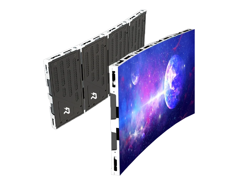
Yes, but you must specifically order "flexible LED modules" from the manufacturer instead of standard rigid fiberglass PCBs. Flexible modules use a pliable silicone rubber or thin polyimide substrate with flexible magnetic points that can bend across convex or concave radiuses. Alternatively, if you are using standard rigid die-cast cabinets, you must buy specialized rental cabinets equipped with angle-adjustment side locks that allow ±5° to ±10° of inter-cabinet curving at the frame seams.
.jpg "Portable Led Display Manufacturers in China_How to Verify Before Ordering")
.jpg "China Rental Indoor LED Video Wall Manufacturers | Buying Guide")